


Turn On: How To Install Switched Accessory Power To Your Motorcycle


Previously, I covered how to install a Powerlet accessory electrical socket. While having access to constant power for accessories is convenient (particularly for maintaining your battery with a smart charger), it has a major drawback: If you leave your electronics on when you shut down the engine, you can easily kill your battery. The best way to prevent this from happening is to make the socket switch itself off with the ignition. Although the task is fairly simple, you’ll need to perform a little detective work before you start.
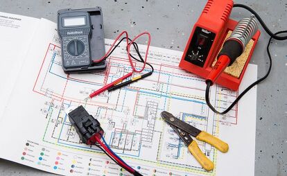
Touring bikes frequently have a fused accessory circuit, but most other motorcycles do not. To suss out a switched circuit, all you need is a sharp eye and a little intuition. You can save some time by consulting the wiring diagram in a service manual. No matter what path you follow, you’re looking for the location of a wire that has power only when the ignition is on.
Choose a non-vital circuit – one that won’t put you in immediate danger should your additional wiring blow a fuse while you’re on the road. Stay away from the headlight and ignition circuits. (Consider the potential consequences if your headlight failed … at night … on a winding mountain road. What about an engine stalled in the middle of briskly moving traffic on an interstate highway?) For this project, I chose the turnsignal circuit since losing it on the road wouldn’t be immediately life-threatening – and would, presumably, be picked up in the next pre-ride check.
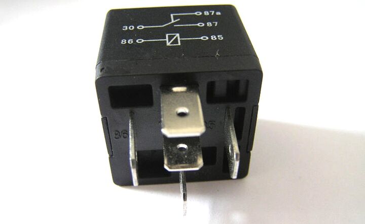
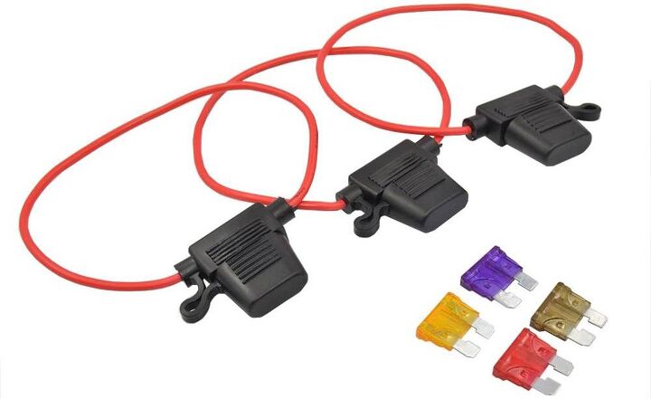
Even if you’re not planning on using a high-power accessory, like driving lights, you shouldn’t just tap in and draw more power on any old pre-existing circuit. To avoid the risk of blowing the fuse, you’ll need to use a relay. In it’s most basic terms, a relay is a switch that uses a little bit of power to throw a bigger, power-hungry switch. For this example, I siphoned just a bit of power from the signal circuit to activate a 15-amp accessory circuit. (A side note: Be sure to calculate the total power drain of your accessories if you’re planning on powering more than just a GPS or phone charger. You don’t want to exceed the limits of your bike’s charging system.)
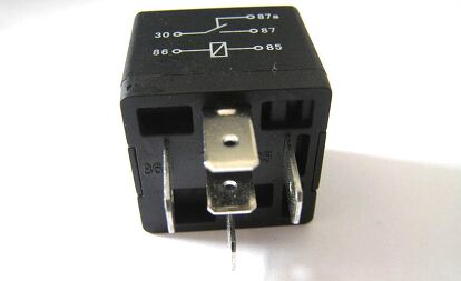
Although you can choose a relay with factory-installed wire leads, relays have a standard wiring pattern which makes it possible for you to slide on your own female spade connectors. When selecting a relay, make sure it is rated for the number of amps of your planned accessory circuit.
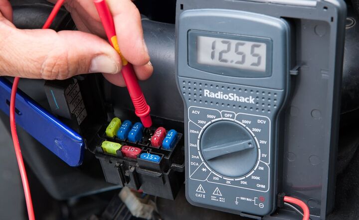
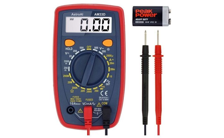
When you think you’ve found your switched power source, verify it. Remove the fuse, and using a voltmeter, check to see which side of the fuse is the hot side. If possible you can flip the fuse box over to ascertain that the color of the wire is associated with the fuse (they can differ with the stated color in the wiring diagram) to ease tracking it to a convenient splice location. You’ll be splicing into the side of the circuit that shows no voltage when the fuse is removed. If you think of the circuit as a pipe sending power from the battery to the chassis ground, you want to tap in to the line downstream of the fuse. This way, if something goes wrong with the relay, the signal fuse will blow and not the bike’s main fuse – which could lead to Very Bad Things I mentioned above.
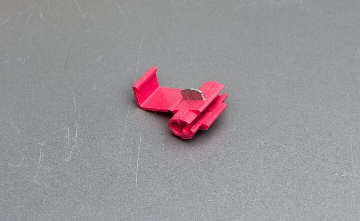
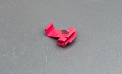
Although they sound like they’d make splices easy, you should avoid crimping wire connectors when making spices into your bike’s wiring harness. They simplify the installation, but they can also cut through some of the actual wire strands, making the wire weaker, higher in resistance, and more prone to failure. Additionally, the high-vibration environment of a motorcycle makes crimp splices more likely to loosen and cause intermittent failures which are a pain to track down.
Soldered connections are the best route to take, offering much more reliable connections. While many novices are terrified of the idea, soldering’s difficulty is vastly overdramatized, and when performed with care, first-timers can create joints that are much stronger than any crimped joint.

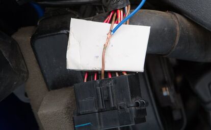
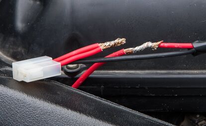
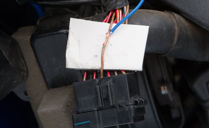
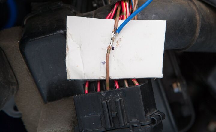
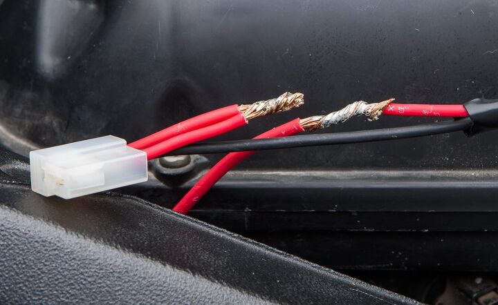
Begin by separating the desired wire from the harness itself. Place a piece of cardboard between the wire and the harness before gently shaving away about two-thirds of an inch of insulation. A sharp knife and a slow pace are all you need. You didn’t forget to disconnect the negative pole of the battery before you began slicing, did you? Accidentally grounding a wire (or knife blade) to the frame is an exciting experience you won’t forget.
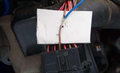
With the relay loosely placed in position, cut the switched power lead (86) to a length just a bit longer than what is required to reach the splice. Strip two-thirds of an inch from the wire end. Wrap the wire tightly enough around the stripped portion of the switched power lead that it can’t be moved when tugged on slightly. This prevents the wires from moving around and helps conduct the heat from the soldering iron to both sets of copper strands.
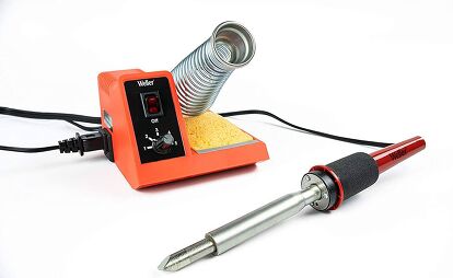
Be sure the soldering iron is powerful enough to heat the gauge of wire you’ll be splicing. Once the iron is up to temperature, tin the tip slightly by melting a small amount of solder to it. The bead of melted solder will make a stronger contact with the wires and help transfer more of the heat.
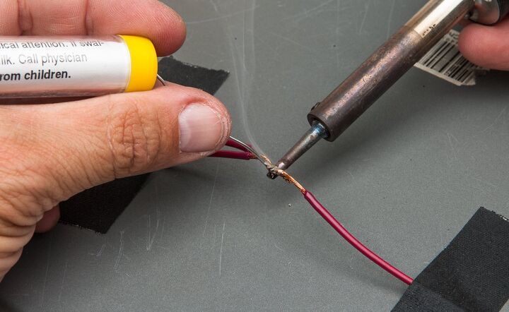
When melting the solder to the wires, try not to touch the iron with the solder. Instead, allow the iron to heat the wire to the point that it melts the solder. Holding the iron below the wires allows the heat to travel upwards while gravity pulls the molten solder down. Capillary action plays an important role in distributing the solder throughout the splice. Touch the iron and solder to a few points on the splice to make sure it is uniformly spread throughout the wire strands. While you want the solder to cover most of the splice, try to avoid leaving big globs of solder on the joint. It looks ugly and will make the splice much larger once it’s covered with tape.


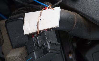
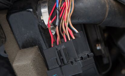
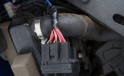
After the splice has cooled, wrap it with electrical tape to prevent any accidental grounding against the frame. After the individual splices have been taped, retape the wiring harness to protect and support the wires. Before replacing the bodywork, check the switched circuit to make sure it is functioning properly. Don’t forget to run it under maximum load. In my example case, that meant powering the turnsignals, the brake light, and relay simultaneously.
You can now enjoy powering your electronic accessories without the worry of killing your battery.
Tools for Splicing

We are committed to finding, researching, and recommending the best products. We earn commissions from purchases you make using the retail links in our product reviews. Learn more about how this works.

Like most of the best happenings in his life, Evans stumbled into his motojournalism career. While on his way to a planned life in academia, he applied for a job at a motorcycle magazine, thinking he’d get the opportunity to write some freelance articles. Instead, he was offered a full-time job in which he discovered he could actually get paid to ride other people’s motorcycles – and he’s never looked back. Over the 25 years he’s been in the motorcycle industry, Evans has written two books, 101 Sportbike Performance Projects and How to Modify Your Metric Cruiser, and has ridden just about every production motorcycle manufactured. Evans has a deep love of motorcycles and believes they are a force for good in the world.
More by Evans Brasfield


Comments
Join the conversation
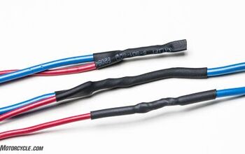
An even better way to seal the new connection is with heat shrink. This is a longer lasting, more water resistant solution than electrical tape.
http://youtu.be/d-j98tkAbh8
Once you have the accessory power installed you can mount an iPhone or Samsung Galaxy on a Sportbike from http://www.motodracing.com/...